Search This Blog

SRAM Data Backup Procedure in fanuc Control


1.  

or 


2.  

  3.

 5.


   6.


SRAM Data Backup Procedure, CNC to Memory Card

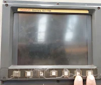
1. CNC Machines display Should be OFF
2. Insert the Compact disc card /Memory card  on the side of the display
3. Press the 6 and 7 numbers key and turn on the cnc machine power ( 6 & 7 numbers key showing by fingers no. 2 )
4. Wait until the system monitor main menu  screen appears
5. After appears system monitor main menu press down key and select SRAM data backup then press Yes key
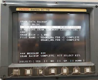
6. SRAM data backup screen will appears 
7. Now press down key and select SRAM backup ( CNC ) Memory Card then after press Yes key
8. Wait until SRAM  backup Complete massage appears 
9.After appears SRAM backup Complete massage press down key and select END then after press Yes
10. Now SRAM data backup Completed and CNC screen will appears

Machining Operation in CNC


Fanuc Alarm Code List for Series


Fanuc Alarm Code List For Series 16i/18i/21i


Alarm 0-999: Fanuc alarm, the alarm if above 1000 maker / machinist / machine tool builder.

Alarm 0-250: programs / settings.

Alarm 300 ~: Pulse Coder, servo, interface, cables.

Alarm 400 ~: SVM, Motor, cable, and mechanics.

Alarm 500 ~ : Over travel.

Alarm 7n01 - 99: Spindle motor problems, SPM, Cable, Mechanical, cutting weight.
Alarm 9n01 - 99:  Same as above.

Alarm 900-975: the problem is on the motherboard. (CPU cards, Axis cards, SRAM, DRAM)

Tool Change position (TCP) procedure for eatch axis in fanuc control


Tool Change position (TCP) procedure for eatch axis in Fanuc control 

For each Axis, If alarm occurred X/Y/Z Axis not a tool change position (TCP) fllow the procedure 

For Maximum Value/Range +X/+Y/+Z  

1. Check bit F70.3/F70.4/F70.5 for eatch Axis on TCP positions make sure if it is 0 then after set TCP positions 
2. Press system key 
3. Press PRAM key 
4. For eatch Axis set +X/+Y/+Z direction,Find Max. Value parameter no 6933,6934,6935 for eatch Axis X/Y/Z by pressing  NO. SRH key and TCP value notedown for example TCP value is 99692 
5. Now +500 add in Current value like 99692+500= 100192
6. TCP Value 100192 put in parameter 6933,6934 & 6935 for eatch Axis X/Y/Z 
7. Now +X/+Y/+Z axis TCP positions set for +X/+Y/+Z direction
8. If TCP positions set properly during Tool change position bit F70.3/F70.4/F70.5 it will change 0 to 1
                  

For Minimum value/Range -X/-Y/-Z 

1. Check bit F70.3/F70.4/F70.5 for eatch Axis on TCP positions make sure if it is 0 then after set TCP positions 
2. Press system key 
3. Press PRAM key 
4. For eatch Axis set -X/-Y/-Z direction,Find Min. Value parameter no 6953,6954,6955 for eatch Axis -X/-Y/-Z by pressing NO. SRH key and TCP value notedown for example TCP value is 5500
5. Now -500 minus in Current value like 55000 -500= 54500
6. Value 54500 put in parameter 6953,6954 & 6955 for eatch Axis X/Y/Z 
7. Now -X/-Y/-Z axis TCP positions set for -X/-Y/-Z direction
8. If TCP positions set properly during Tool change position bit F70.3/F70.4/F70.5 it will change 0 to 1

M Code List of BFW HMC650


Keep Relay List of BFW HMC650


Spindle Orientation procedure in fanuc control


Spindle Orientation procedure

1. Press systems key
2. Press diagnosis function key
3. Search parameter 445 by pressing NO. SRH key and check spindle position in parameter 445 and note down the position value
4. Press system key
5. Press PARAM key and search parameter 4077 by pressing NO. SRH key
6. Manually tenon position set for orientation position whare you want 
7. Again Search parameter 445 by pressing NO. SRH key and check spindle position in parameter 445,Example like 2111
8. Put Spindle position in parameter no 4077 
9. Now spindle orientation set
 

Axis Refrence (Zero Return) procedure of eatch axis in fanuc control


Axis Refrence (Zero Return) procedure

  1. Move the axis to where you want to zero return position 
  2. Select "MDI" mode
  3. Press the function key “OFFSET SETTING”
  4. Press the  “SETTING” key
  5. Move the cursor to “PARAMETER WRITE” . May need to page up or down to get to the top of the Parameter numbers.
  6. Turn on PWE (Parameter Write) make it a 1
  7. Press the  "SYSTEM" key
  8. Press the "PARAM" key
  9. Type1815 and press "No.Search" . This should bring up parameter 1815.
  10. Arrow down to whichever axis you want to change X,Y,or Z.
  11. Change bit of APZ 1 to 0 (This will delete the current reference zero). 
  12. Alarm will occurred need to ZRN
  13.  Power off machine for one minute and power up
  14. Go back to the parameter 1815 and make bit of APZ  0 to 1
  15. Power off machine for one minute and power up
  16. Now new home position will be set


Axis in CNC Machines (Example)


Siemense Interconnection Drive+NCU


Type of Cylinder Mounting


Encoder and Tpyes of Encoder


Encoder: In general an encoder is a device or process that converts data from one format to another. In position sensing, an encoder is a device which can detect and convert mechanical motion to an analog or digital coded output signal. More specifically, it measures the position, while velocity, acceleration and direction can be derivated from the position in either linear or rotary movement.

Types of Encoder are:


MAG Make CNC Machines Electrical Panel


MAG Make CNC Machine