Search This Blog

MTBF ( Mean Time Between Failures )

What is mean time between failures? 

MTBF (mean time between failures) is the average time between repairable failures of a technology product. The metric is used to track both the availability and reliability of a product. The higher the time between failure, the more reliable the system.

MTBF calculation Formula:


MTBF Example :

Over a period of time the following information is available:

Total Production Time (PT): 1,240 minutes 

Total Downtime (DT): 1.5 hours (watch the unit of measures)

Number of Failures (F): 25

Determine the MTBF:

The first step is to determine the Uptime (UT) which = PT - DT

Uptime (UT) = 1,240 minutes - 90 minutes = 1,150 minutes

MTBF = UT / F = 1,150 / 25 = 46 minutes


MTTR ( Mean Time To Repair )

What is MTTR?

Mean time to repair (MTTR) is a maintenance metric that measures the average time required to troubleshoot and repair failed equipment. It reflects how quickly an organization can respond to unplanned breakdowns and repair them.

MTTR calculates the period between the start of the incident and the moment the system returns to production. 

Mean time to repair (MTTR): As described above, MTTR is the average time it takes for a failed system to be fixed and restored to full functionality. It is a relative measure, and therefore, depending on the system, could be measured in anything from minutes to days.


This takes into account the time to:

1.Notify technicians

2.Diagnose the issue

3.Fix the issue

4.Allow the equipment to cool down

5.Reassemble, align, and calibrate the asset

6.Set up, test, and start up the asset for production

Calculate MTTR by adding up the total time spent on repairs during any given period and then dividing that time by the number of repairs.

Mean Time To Repair = (Total downtime) / (number of failures)

MTTR Example :

Over a period of time the following information is available:

Total Production Time (PT): 1,240 minutes 

Total Downtime (DT): 1.5 hours (watch the unit of measures)

Number of Failures (F): 25

Determine the MTTR:

MTTR = Total Downtime / Number of Failures = 90 minutes / 25 failures

MTTR = 3.6 minutes per failure

OEE ( Overall Equipment Effectiveness )

What is OEE?

Overall equipment effectiveness is a maintenance KPI that measures an asset’s level of productivity. OEE is a combination of three factors that tell you how efficient an asset is during the manufacturing process: asset availability, asset performance, and production quality.

1. Availability – How often does the asset function when needed?

2. Performance – How much does the asset produce?

3. Quality – How many high-quality items does the asset produce?

When an asset operates with an OEE of 100%, it means that every item it produces is without defect (quality), it is producing as fast as possible (performance), and it experiences no unplanned downtime (availability).

OEE Factors :


OEE Calcutation Formula :

OEE = Availability (A) × Performance (P) × Quality (Q) 


Benchmarking OEE :

Ideal Availability 90%  Normal 79%

Ideal Performance 95% Normal 80%

Ideal Quality 99.9%  Normal 95%

Ideal OEE 85%  Normal 60%

How is OEE used?

Overall equipment effectiveness is an indicator of how efficient the manufacturing process is. It can be used to identify underperforming assets and connect poor performance with one or more of the three main factors (availability, performance and quality). Once the source of the problem is pinpointed, the underlying issues can be investigated and improved.

Six Big Losses :


Maintenance and Types of Maintenance

What is Maintenance?

Maintenance, otherwise known as technical maintenance, refers to a set of processes and practices which aim to ensure the continuous and efficient operation of machinery, equipment, and other types of assets typically used in business. Diligence in implementing an effective maintenance program is essential to the successful performance and longevity of machinery, assets, facilities, and entire businesses.


Types of Maintenance :

There are different types of maintenance work, each designed for specific scenarios.

1. Breakdown Maintenance 

2. Planned Maintenance 

A. Preventive Maintenance 

B. Predictive maintenance 

C. Corrective Maintenance 

3. Routine Maintenance 


1. Breakdown Maintenance 

Breakdown maintenance, sometimes called run-to-failure maintenance, occurs when an asset completely breaks down and needs repair to resume operation.

The breakdown maintenance is a type of maintenance that involves using a machine until it completely breaks down and then repairing it to working order.For example, this type of maintenance would occur if you wait until a machine stops working before fixing it.

Breakdown maintenance is triggered by either:

☆ A planned event, such as run-to-failure maintenance.

☆ An unplanned event, such as the need for reactive or corrective maintenance.

2. Planned Maintenance

Where routine maintenance may happen on a daily, weekly, or monthly basis, planned maintenance may be scheduled once per year or as needed. This is because planned maintenance is more time-consuming, expensive, and thorough—often requiring the services of a specialist. In the context of maintaining an air-conditioning unit, routine maintenance is taking out and washing the filters once per month, while planned maintenance is hiring an HVAC professional to check refrigerant levels, possible leaks, and measure airflow through the evaporator coil.

A. Preventive Maintenance 

Preventive maintenance (PM) is the regular and routine maintenance of equipment and assets in order to keep them running and prevent any costly unplanned downtime from unexpected equipment failure.Preventive maintenance is the act of performing regularly scheduled maintenance activities to help prevent unexpected failures in the future. Put simply, it's about fixing things before they break.

Preventive maintenance (PM) is a simple and popular maintenance strategy. Preventive maintenance, also known as preventative maintenance, can help extend asset life, increase productivity, and ultimately decrease maintenance spending.

B. Predictive Maintenance

This maintenance type focuses on techniques used to determine the appropriate schedule for planned and corrective maintenance. Its primary goal is to predict, through a variety of testing methods, when a machine will start experiencing severe wear and tear so corrective maintenance can be scheduled without affecting productivity goals and before the machine breaks down.

C. Corrective Maintenance 

Corrective maintenance is a maintenance task performed to identify, isolate, and rectify a fault so that the failed equipment, machine, or system can be restored to an operational condition within the tolerances or limits established for in-service operations.

Corrective maintenance covers maintenance tasks that are undertaken to identify, isolate and repair a fault in order to restore equipment, a machine or a system to an operational condition so it can perform its intended function.

Corrective maintenance is often associated to breakdowns or reactive maintenance and can include troubleshooting, disassembly, adjustment, repair, replacement and realignment.

3. Routine Maintenance

This type of maintenance, also referred to as preventive maintenance, is implemented on a fixed schedule and typically includes activities such as inspecting, cleaning, washing, replacing, and checking. It is typically performed in the downtime between shifts or on weekends to avoid affecting productivity goals. Routine maintenance has two objectives; to identify existing issues so they can be corrected ASAP and to prevent possible issues from becoming a reality through consistent care.

SV0368 B axis Serial data error alarm


This type of problem occurs whenever the B axis encoder or encoder cable is damaged or not conducted. 

Remedy:
Check the B axis encoder cable is properly connected.

701 Over Heat Fan Motor Alarm


This type of problem occurs when the HMI back side cooling fan is not running.

Remedy:

Check the cooling fan of NC controller is it bad or correct if it is bad just replace it.

Note:   

The cooling fan will be found on the back side of the HMI.


Cooling fan show in Picture above 

Cutting Tool Insert

Cutting tool inserts are replaceable attachments for cutting tools that typically contain the actual cutting edge. 

Cutting tool inserts applications include:

1.Boring
2.Construction
3.Cutoff and parting
4.Drilling
5.Grooving
5.Hobbing
6.Milling
7.Mining
8.Sawing
9.Shearing and cutting
10.Tapping
11.Threading
12.Turning
13.Brake rotor turning


Cutting Tool Insert shape :


Screw Driver

Screw driver is a tool, manual or powered, used for turning screws. A typical simple screwdriver has a handle and a shaft, ending in a tip the user puts into the screw head before turning the handle.


1825 SERVO LOOP GAIN PARAMETER


Valid data range 1 to 9999
Set the loop gain for position control for each axis.When the machine performs linear and circular interpolation (cutting), thesame value must be set for all axes. When the machine requirespositioning only, the values set for the axes may differ from one another.As the loop gain increases, the response by position control is improved.

1428 REF FEEDRATE PARAMETER


1821 REF. COUNTER PARAMETER


Valid range 0 to 99999999 
Set the size of the reference counter.

Note:
When this parameter has been set, the power must beturned off before operation is continued.

1434 MAX FEEDRATE AT HANDLE PARAMETER


1427 EX DEC F RAPID PARAMETER


1425 REF. RETURN FL PARAMETER


Set  feedrate (FL rate) after deceleration when the reference position returnis performed for each axis.

1421 RAPID OVERRIDE F0 PARAMETER


Set the F0 rate of the rapid traverse override for each axis


1430 MAX CUT FEEDRATE PARAMETER


Specify the maximum cutting feedrate for each axis.A feedrate for each axis is clamped in cutting feed so that it does not exceed the maximum feedrate specified for each axis

Note:
1. This parameter is effective only in linear and circularinterpolation.
2. If the setting for each axis is 0, the maximum feedratespecified in parameter No.1422 is applied to all axes and thefeedrate is clamped at the maximum feedrate

1424 MANUAL RAPID FEEDRATE PARAMETER


Set the rate of manual rapid traverse when the rapid traverse override is100% for each axis

1815 SERVO AXIS REFERENCE PARAMETER


When the parameter 1815 APZ column changes to a zero, this means the absolute encoder in the respective axis has lost its zero position. When you turn it back to a 1, this enables you to move the axis back to zero if it is not.

1420 RAPID FEEDRATE PARAMETER


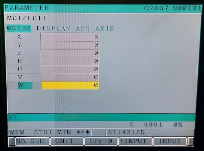
3132 DISPLAY ABS AXIS PARAMETER


 3132 sets the absolute axis letter

3133 Display Rel Axis Parameter


Check Parameter 3133, this is ASCII control characters for the axis letters. If set to 0's then the axis names on the screen for relative will be the same as all the others.

3133 sets the relative axis letter name

1320 and 1321 STROKE (SOFT) LIMIT PARAMETER


You can change the soft limits with parameter 1320 and 1321. Move the mill to the farthest location you want to travel and then look at the axis "Machine" location in the all POS view. Take that number plus whatever margin and put that in the stored stroke limit.

The value of stored stroke is .001 mm or .0001 inch

Soft limits use software to protect your CNC machine from movements that exceeds a set position. No hardware is required when using soft limits since the software uses the encoder counts. It is important that the machine is correctly homed since soft limits use the current position to determine if the axis is allowed to travel within the minimum and maximum defined area. This area is also known as the Soft Max and Soft Min.


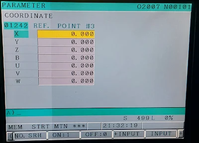
1240,1241 and 1242 REFERENCE POINT PARAMETER


1240,1241 & 1242 is just the 1st,2nd and 3rd reference point that you set from your origin position.parameters 1240,1241 &1242 act more like G54-G59 workcoordinates.


Compressor

A compressor is a mechanical device that increases the pressure of a gas by reducing its volume. An air compressor is a specific type of gas compressor. Compressors are similar to pumps: both increase the pressure on a fluid and both can transport the fluid through a pipe. 


 Compressor show in Picture above 

1001,1002 &1004 alarm


 Remedy:

1. Check any one MPCB for tripped 

2. Check SMPS should ON 

Jog Unit Operation in CNC Machine


Basic operation of a jog unit is as follows:


1.Select an axis with the Axis Select Switch.


2.Use the Jog Feed Keys:


a.Select either the + or – Jog Feed Keys.


b.Adjust Jog Feed Override to override the programmed axis feedrate.


OR


3.Use the Hand Wheel Multiplier:


a.Select a hand wheel resolution with one of the Hand Wheel Multiplier Keys.


b.Rotate the Jog Hand Wheel.

1852 BACKLASH RAPID PARAMETER


Backlash: Backlash parameter values allow the control to compensate for the physical limitations of the ballscrew when changing tool direction


1852 Backlash Rapid parameter show in Picture above 

Valid data range -9999 to +9999Set the backlash compensating value used in rapid traverse for each axis.

1851 BACKLASH PARAMETER


Backlash: Backlash parameter values allow the control to compensate for the physical limitations of the ballscrew when changing tool direction. 


1851 Backlash parameter show in Picture above 

Valid data range –9999 to +9999Set the backlash compensating value for each axis.

When the machine moves in a direction opposite to the reference positionreturn direction after the power is turned on, the first backlashcompensation is performed.

Remote (DNC) Mode Operation in CNC Machine

DNC OPERATION : By activating automatic operation during the DNC operation mode (REMOTE), it is possible to perform machining (DNC operation) while a program is being read in via reader/puncher interface, or remote buffer. To use the DNC operation function it is necessary to set the parameters related to the reader/punch interface and remote buffer in advance.

To complete this procedure follow the next procedure:

1. Search for the program to be executed.

2. Press the REMOTE switch on the machine operator’s panel to set REMOTE mode, then press cycle start switch. The selected file is executed.During DNC operation, the program currently being executed is displayed on the program check screen and program screen.The number of displayed program blocks depends on the program being executed.

DNC Operation procedure with memory card:

1. Set the parameter of No.0020 to 4 in the setting screen in advance.

2. Change to REMOTE mode.

3. Press PROG function key on the MDI panel.

4. Push “+” soft key twice.

5. When “DNC-CD” soft key is pressed, the following screen is displayed.The screen can be scrolled by page key. An arbitrary file number is input, and “F SRH” soft key is pressed. Then the arbitrary file name is displayed at the top of DNC operation (memory card) screen.

 6. Input the file number which is going to be executed

7. Press the “DNC-ST” soft key, the file name will be displayed in the right side of DNC FILE NAME:For example, DNC FILE NAME:O00538. Press the CYCLE START button to execute the program selected.

Auto Mode Operation in CNC Machine

MEMORY OPERATION (AUTO MODE) :

Programs are registered in memory in advance. When one on these programs is selected and the cycle start switch on the machine operator’s panel is pressed, automatic operation starts, and the cycle start LED goes on.When the CYCLE STOP switch in the machine operator’s panel is pressed during automatic operation, this operation is stopped temporarily. When the cycle start switch is pressed again, automatic operation is restarted.When the RESET key on the MDI panel is pressed, automatic operation terminates and the reset state is entered. 

To complete this operation follow the next procedure:

1. Press the MEMORY(AUTO) mode selection switch.

2. Select the program from the registered programs doing the following steps:

• Press PROG to display the program screen.• Press “+” soft key.

• Press “DIR” soft key and the program library will be displayed.

• Enter a program number using the numeric keys. 

• Press the O SRH soft key.

3. Press the CYCLE START switch on the machine operator’s panel. Automatic oper-ation starts, and the cycle start LED goes on. When automatic operation termi-nates, the cycle start LED goes off.

4. To stop or cancel memory operation midway through, follow the steps below:

• Stopping memory operation.

Press the CYCLE STOP switch on the machine operator’s panel. The feed hold LEDgoes on and the cycle start LED goes off. The machine responds as follows:

When the machine was moving, feed operation decelerates and stops.When dwell was being performed, dwell is stopped.When M, S, or T was being executed, the operation stopped after M, S, or T is finished.

• Terminating memory operation.

Press the RESET key on the MDI panel.Automatic operation is terminated and the reset state is entered. When a reset is applied during movement, movement decelerates then stops.


MDI Mode Operation in CNC Machine

MDI OPERATION: In the MDI mode, a program consisting of up to 10 lines can be created in the same format as normal programs and executed from the MDI panel. MDI operation is used for simple test operations.In order to complete this operation, follow the next procedure:

1. Press the MDI mode selection switch.

2. Press the PROG function key on the MDI panel to select the program screen.

3. Prepare a program to be executed by an operation similar to normal program edit-ing. M30, specified in the last block can return control to the beginning of the pro-gram after operation ends. Word insertion, modification, deletion, word search, address search, and program search are available for programs created in the MDI mode.

4. To entirely erase created program in the MDI mode, use one of the following meth-ods:• Enter address, and then press the DELETE key on the MDI panel.• Alternatively, press the RESET key.

5. To execute a program, set the cursor on the head of the program. Push CYCLE START button on the operator’s panel. By this selection, the prepared program will start. When the program end (M02, M30) or ER (%) is executed,The program will be erased and the operation will end. By command of M30, control returns to the head of the prepared program.

6. To stop or terminate MDI operation in midway through, follow the next steps:

• Stop MDI operation.

Press the CYCLE STOP switch on the machine operator’s panel. The feed hold LED goes on and the cycle start LED goes off.

• Terminate MDI operation.

Press the reset key on the MDI panel. Automatic operation is terminated and the reset state is entered. When a reset is applied during movement, move-ment decelerates then stops.

FANUC FILES BACKUP PROCEDURE in CNC Machine

Please prepare the compact flash card.

I. Step 

(Prepare operation)

1. Smoothly put the COMPACT FLASH CARD inside the M-CARD slot of LCD.

2. Press “EDIT” button to change to edit mode.

3. Press “SYSTEM” key on the MDI panel until parameter screen comes out.

4. Press “+” twice using the soft key until ALL IO displays below the LCD.

5. Press “ALL IO”.

(Backup the parameter)

6. Press “< ” to return to the previous page.

7. Press “PARAM” soft key on the LCD screen.

8. Press “OPRT” soft key.

9. Press “PUNCH” soft key.

10. Press “EXEC” soft key (OUTPUT will be display on the screen, all the parameter will output to the Flash Card as CNCPARAM.DAT).

(Backup the MACRO)

11.Press “< ” to return to the previous page.

 Backup of data files procedure:

12. Press ”+” soft key to change to the next page.

13. Press “MACRO” soft key.

14. Press “OPRT” soft key.

15. Press “PUNCH” soft key.

16. Press “EXEC” soft key (OUTPUT will be display on the screen, all the macro vari-ables will output to the Flash Card as MACROVAR.DAT).

(Backup the PITCH)

17. Press “< ” to return to the previous page.

18. Press “PITCH” soft key on the LCD screen.

19. Press “OPRT” soft key.

20. Press “PUNCH” soft key.

21. Press “EXEC” soft key. (OUTPUT will be display on the screen, all the pitch com-pensation will output to the Flash Card as PITCHERR.DAT).

(Backup the work offset)

22. Press “< ” to return to the previous page.

23. Press “WORK” soft key.

24. Press “OPRT” soft key.

25. Press “PUNCH” soft key.

26. Press “EXEC” soft key. (OUTPUT will be display on the screen, all the parameter will output to the Flash Card as WORK-G54.DAT).

(Backup the Magazine)

27. Press “< ” to return to the previous page.

28. Press ”+” to the next page.

29. Press “MAG”.

30. Press “OPRT”.

31. Press “PUNCH”.

32. Press “EXEC “ (OUTPUT will be display on the screen, all the parameter will output to the Flash Card as MAGAZINE.DAT).

(Backup the Tool management)

33. Press “< ” to return to the previous page.

34. Press “TOOL-MNG” soft key.

35. Press “OPRT” soft key.

36. Press “PUNCH” soft key.

37. Press “EXEC” soft key. (OUTPUT will be display on the screen, all the parameter will output to the Flash Card as TOOL-MNG.DAT).

II Step

(Backup the PLC software)

1. Put the Flash Card into the slot on the LCD

2. Press “EDIT” button to change to change edit mode.

3. Press “SYSTEM” on the MDI panel until parameter screen comes out.

4. Press “PMC” soft key. 

5. Press “I/O”.

6. Select the page as following (move the cursor, and use the soft key to select the correct data type).M-cardWriteLadderPMC-SB.000

7. Press “EXEC” soft key. (OUTPUT will be display on the screen, PLC software will output to the Flash Card as PMC-SB.000).

(Backup the PLC parameter)

8. Move the cursor to the “DATA TYPE=”.

9. Press the “PARAM” soft key on the LCD.

10. Select the page as following.M-cardWritePARAMPMC-SB.PRM

11. Press “EXEC” (OUTPUT will be display on the screen, PLC software will output to the Flash Card as PMC-SB.PRM).

III Step:

SRAM backup procedure:

1. Power OFF the machine.

2. Put the flash card into the slot.

3. Press the most right side two soft key on the LCD screen and hold.

4. Press the CNC power on push button.

5. Wait until the CNC system screen comes out.

6. Press the “DOWN” soft key to move the cursor to the item 5 (is highlighted):“5-System Data Backup”

7. Press “SELECT” soft key will display two choices:“1. SRAM BACKUP(CNC −− Flash Card)”“2..................................................”

8. Make sure the cursor is on the first line.

9. Press “SELECT” soft key and you will be asked “Backup SRAM Data OK?” 

10. Select “YES” to continue. (or “NO” to return to previous menu)

11. Wait couple of seconds. The screen will display complete information.

12. Press “SELECT” soft key.

13. Press the “DOWN” soft key until the cursor moves to item : END. 

14. Press “SELECT”.

15. Press the “DOWN” soft key until the cursor moves to item : END. 

16. Press “SELECT” soft key.

17. Press “YES” soft key.

18. Finish, the CNC system will boot up.


Edit Magazine data for Fanuc Control in CNC Machine

Edit the Magazine data procedure is as follows :

1. Press MDI button.

2. Press OFFSET/SETTING.

3. Press “+”soft key.

4. Press TL-MNG soft key.

5. Press MAG soft key to enter the magazine data page.

6. Press OPRT soft key.

7. Press EDIT soft key to start editing the magazine data.

8. Press OPRT soft key again after editing is finished.

9. Press END soft key to exit magazine data the editing mode

Edit Tool Data in CNC for Fanuc Control

Edit the tool data procedure is as follows :

1. Press MDI button.

2. Press OFFSET/ SETTING.

3. Press “+” soft key.

4. Press TL-MNG soft key.

5. Press TOOL soft key to enter the tool data page.

6. Press OPRT soft key.

7. Press EDIT soft key to start editing the tool data.

8. Press OPRT soft key gain after editing is finished.

9. Press END soft key to exit tool data the editing 

Function Modes in CNC Machines

TEST FUNCTION MODES :

Single Block: Single Block Mode executes part program block by block.Single block mode is implemented to toggle On/Off with press of button.Pressing the single block switch starts the single block mode. When the cycle start button is pressed in the single block mode, the tool stops after executing a single block in the program. Check the program in the single block mode by executing the program block by block.5.1.2 

Block Delete: Skip execution of program Block (/). Multi level Block Skip is not supported. Block Delete is implemented to toggle On/Off with press of button.

Optional Stop: Option Stop is implemented to toggle On/Off with press of button. Executing program will stop at M01 when option stop button is On. Operator needs to push CYCLE START button to restart the program. It does not affect the program when the option stop button is Off.

Program Stop: Program Stop indicator LED is lit when part program execution is stopped by M00 or M01 part program.

Machine Lock: Machine Lock (Test Mode) enables execution of part program without axis motion, but M/S/T command still is able to execute. This button is for test purposes. Machine lock is implemented to toggle On/Off with press of button.

Dry Run: This feed rate forces program federate to fixed “dry run” rate to speed non-cutting testing of part programs. Dry Run is implemented to toggle On/Off with press of button except AUTO and REMOTE mode. If the machine is in AUTO or REMOTE mode, operator can turn On DRY RUN by pressing FUNC + DRY RUN buttons and turn it Off by pressing DRY RUN button.


Operation Mode in CNC Machines

8 operation mode available in CNC machine,Operation mode is as follows:


Operation Mode show in Picture above 

Auto (Memory) Mode: Auto Mode is also called Memory Mode. Automatic operation of part program selected from program files registered in control’s program directory.

Edit Mode: Edit mode enables entering and editing of part programs stored in control’s part program directory. Part programs stored on optional Data Server or memory card inserted in PCMCIA card slot are not available for editing. Programs must be edited before loading to storage media.

MDI (Manual Data Input) Mode: MDI mode is used for simple test operation. In the MDI mode, operator can create and execute a program consisting up to 10 lines from the MDI panel, which is in the same format as the normal program.

Remote Mode: Remote mode is also called DNC mode. In the mode, it is possible to perform machining while a program is being read in via reader/puncher interface, or remote buffer. Operator can, also, perform machining with execution of the program in the memory card, which is installed in the memory card interface located on the left side of the screen.

Reference Return Mode: Reference Return gives an opportunity to return all the axes to the machine zero position.

Jog Mode: In the continuous jog mode, pressing the direction switch on the operator’s panel moves the tool along with the selected axes in the selected direction.

INC JOG (Incremental Jog Feed) Mode: In the incremental mode, pressing a feed axis and direction selection switch on the machine operator’s panel moves the tool one step along the selected axis in the selected direction.2.3.8

Handle (MPG) Mode: In the handle mode, operator can move the axes by rotating the manual pulse generator on the operator’s pane

1423 JOG FEEDRATE PARAMETER FOR FANUC CONTROL


Jog: Pressing the button continuously moves the tool along the axis in the selected direction.

A jog  is used to manually jog the axis and control machine operation. Hand-held, or remote, jog units can be removed from the console and carried closer to the work piece


1423 Jog Feedrate parameter for fanuc control show in Picture above


Welding Machine

A welding machine is a device used to join materials together. Welding machines produce heat that melts metal parts so that these parts can be joined. Thus, when it cools, it becomes a fixed and resistant joint.

There are 3 main welding techniques - MIG, TIG, Arc welding to name a few.Each need a specific welding machine to be used.


PARAMETER WRITE ENABLE (PWE) in CNC Machine


Parameter Write Enable procedure are :


1. Put it in MDI mode

2. Put in Program key switch ON Condition 

3. Hit the offset key

4. Hit the settings cursor key

5. In Parameter write put 0 to 1

6. Now Parameter Write enable process are Completed 


1010 HYDAULIC OIL LEVEL LOW ALARM


 Remedy:

1. Check Hydaulic oil level should maintain 

2. Check Hydaulic oil level low proximity sensor should be ok

1850 GRID SHIFT PARAMETER


Grid shift is a parameter that moves the axis, a determined amount to a home loaction. Jumping grid happens when the machine jumps to the next pulse from the feedback system

Valid data range 0 to 99999999A grid shift is set for each axis

To shift the reference position, the grid can be shifted by the amount set inthis parameter. Up to the maximum value counted by the referencecounter can be specified as the grid shift

Note:
When this parameter has been set, the power must beturned off before operation is continued

1040 No Tool in Spindle Alarm


 Remedy :

1. Check Hydaulic pressure should be 60 to 80 bar

2. Check clamp without tool X2.2 signal should not fluctuate

3. Check Tool clamp signal X2.3 should not fluctuate 

4. Check Tool release signal X2.4 should not fluctuate

5.  Point no 2,3 & 4 if occurred check its settings on OTT controller 

6. Check spindle clamping force should be maintained 


X2.2,X2.3 and X2.4 signals show in Picture above 

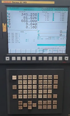
Servo Load Meter Check in Fanuc HMI Display


Fanuc HMI display show in Picture above 

Servo Load Meter check procedure are :

1. Put it in Auto/Edit/MDI/Remote/Ref/ Jog/ Inc/Handle any one mode

2. Hit the POS key

3. Hit the right hand side cursor softkey 1 time

4. Hit the Monitor key

5. Now servo load meter showing 


               Servo load meter show in Picture above 


Date and Time Setting in Fanuc HMI Display


Fanuc HMI display show in Picture above
 
Date and time setting procedure are :

1. Put it in Auto/Edit/MDI/Remote/Ref/ Jog/ Inc/Handle any one mode

2. Hit the offset/settings key

3. Hit the settings softkey

4. Now do parameter write enable put 1

5. Scroll down until you see the date and time

6. Then highlight the Year or Month or day and  Hour or minute or Second section and put in the new value

7. Hit input key

8.Now date and time are set


Date and Time settings are show in Picture above 

Pneumatic Push-in Connector


Pneumatic push-in fittings, also called push to connect fittings, provide a leak-free means of easily connecting hoses in your compressed air system.

Types of Push-in Connectors


Most commonly used connectors 


PNP and NPN Sensor wiring


3 wire PNP and NPN sensor wiring with contector show in Picture above 


3 wire PNP and NPN sensor wiring with PLC  show in Picture above 

PNP Wiring :

This is sometimes referred to as sourcing (+24VDC) the load or positive switching. The black wire of our sensor is connected to the PLC input. The common point of the PLC input and the blue wire is connected to the 0VDC supply. The brown wire of our sensor is connected to the 24VDC supply. You can see in above Picture the proximity switches/sensor connects the load to 24VDC.

NPN Wiring :

This is sometimes referred to as sinking (0VDC) the load or negative switching. The black wire of our sensor is connected to the PLC input. The common point of the PLC input and the brown wire is connected to the 24VDC supply. The blue wire of our sensor is connected to the 0VDC supply. You can see in above Picture the proximity switches/sensor connects the load to 0VDC.

3-wire DC PNP or NPN sensor:

PNP = Switched Positive

NPN = Switched Negative

PFBM alarm code 1


PFBM alarm code 1 show in Picture above 

Power Failure Backup Modules (PFBM) provide sufficient energy for a safe stop and retraction of the spindle and servo axes

Remedy :

Cause 1 : 


Cause 2: Check IGBT of PFBM maybe faulty, If found faulty replaced it