Search This Blog

Electrical Maintenance Questions & Answer

 01. What is Mean by Electrical  Maintenance? 

Ans: For continuous operation of the electrical system we have to repair, diagnosis a fault, observation can be done by Maintenance to run it continuously. 

02. What are the types of Maintenance? 

Ans:  The types of maintenance are:

a. Preventive Maintenance 

b. predictive maintenance 

c. Corrective maintenance 

03. How we can check cable continuity?

Ans: It can be checked by using Multimeter. Keeping the knobs on cable both sides and when there is a sound then we decide cable is good. 

04. What are the faults occur on the HT breaker? 

Ans: Overvoltage, overcurrent,  undervoltage, earth fault, DC supply fail. 

05.  How you can take megger (IR) value? 

Ans: Megger value can be taken with phase to phase and phase to earth. i. e.  R-Y, Y-B, B-R and R-E, Y-E, B-E.

06. What is mean by PERCOW or work permit? 

Ans: While doing any work on a live electrical system you need a PERCOW means a permit for work commissioning from the authorized person. 

07. What is the toolbox talk? 

Ans: During the maintenance before work starts it is the responsibility of Engineer to give toolbox talk means which section is disconnected, from where there is supply and work within the cordon area. 

08. What is mean by changeover? 

Ans: If we want to take shut down on a particular section of substation than we have to manage load or shifting load from one source to another or one transformer to other transformers. 

09. How many times Maintenance is done? 

Ans: It was done by Daily, weekly, Monthly, Quarterly, and yearly.

10. What are the types of panels?

Ans: HT, LT, sub LT, RTU( Remote terminal unit) APFC (Automatic power factor correction ), MCC( motor control circuit), and PCC( power control circuit ). 

11. What are the six golden rules of safety? 

Ans: The six golden rules of safety are:

1. Disconnect all sources of power.

2. Follow Log out tag out (LOTO) on a particular feeder

3. Check the supply continuity by using an HT detector.

4. Do all phases properly earthed by using the earth rod.

5. Cordon the adjacent area.

6. Ensure proper personnel is deployed for work.

12. Electrical shock caused by voltage or current? 

Ans: It may be caused by current not voltage.

13. Which tools are used in Electrical Maintenance? 

Ans: Multimeter, Megger, Spanner ser, Rachet set, HT, LT hand glows, Tester, clamp meter, insulation tape, torch, plier, nose plier, alen key, etc.

14.  What is the difference between Dry-type transformer  & oil type transformer? 

Ans: In dry type air is used as an insulating medium, the cost is high, less maintenance, used in public places.in oil type transformer oil is used as insulating media, the cost is less, maintenance more, high efficiency, etc.

15. Tell me the ratings of Transformer, induction motor, DG, generator? 

Ans: 

a. Transformer in KVA,  MVA. 

b. Motor in KW MW.

c. DG in KVA,  MVA.

d. Generator in KVA, MVA.

e. UPS in KVA.

16.  What is the lamp indication on HT breakers? 

Ans: ON indication, OFF indication, breaker in-service indication, the breaker in test position indication, breaker trip position indication, Spring charged indication.

17.  What are the types of power? 

Ans: 

1. Real or active power

2. Reactive power

3. Apparent power.

18. What are MCC and PCC? 

Ans: MCC: motor control circuit.

         PCC: a power control circuit

PCC is more powerful than MCC.

19. Do you know the difference between AIS and GIS? 

Ans: AIS: Air-insulated substation. It uses air as an insulating media, the cost is less, Maintenance is more, space required more that’s why the demand for AIS is less nowadays.

GIS: Gas-insulated substation  SF6( Sulfur hexafluoride) gas used as an insulating media, space required less, less maintenance, the cost is high,  required a skilled person nowadays in the compact area where space is less there GIS is used.

20. Tell me what parameters you are going to check while doing maintenance of dry type transformer? 

Ans: During maintenance first you have to shut down transformer after that follow six golden rules, then you have to clean it by using blower after that clean it with cotton wastes, after that check the tightness of HV side and LV side after that take megger or IR value and noted.

21.  Can you give the classification of faults in the power system? 

Ans: There are mainly two types of faults:

1. Series faults

     a) Single conductor open

     b) Two conductor open

2. Shunt fault 

     A) Balanced fault

             1) Three-phase fault

             2) Three-phase to ground

      B) Unbalanced fault 

            1) line to ground fault

            2) The line to line fault

            3) Double line to ground fault.

22. What is the long-form of HVAC, STP, WTP, BMS, and UPS? 

Ans: 

HVAC: Heating, ventilating and air conditioning

STP: Sewage treatment plant

WTP: water treatment plant

BMS: Building Management system.

UPS: Uninterrupted power supply.

23. Why we installed the capacitor bank? 

Ans: To improve the power factor.

24. What is the earthing pit? Which materials are used for earthing pits?

Ans: As we know current always follow the path of least resistance and to divert the maximum current away from an electrical circuit earthing pits are necessary. 

The material used is charcoal, salt, and water.

25.  How DG start? 

Ans: It can be started by Manually or Automatic mode.

26. Do you know DG Check? 

Ans: yes, 

           1.) A check

           2.) B check 

            3) C check 

            4) D check

27. What is SCADA?  How it is used in a substation.

Ans: Supervisory control and data acquisition. 

SCADA  is remote control of your substation were you able to know the current status of all substation equipment. You can also make the on and off status of any equipment like Breakers, Transformers, Incomers, APFC, etc.

28. What is bus coupler, busbar, isolator, and incomer? 

Ans:  It a device where it is coupled with another device without interrupting the system. In case of emergency for shifting the load we can on the bus coupler.

Busbar: It is a bundled conductor on which several( more than two) conductors are mounted.

Isolator: It can be operated only in no-load condition and installed at before and after the circuit breaker.

Incomer is a nothing but breaker but incoming supply is given to this breaker, if this breaker tripped, all feeders which are on this incomer are off.


AC Motor construction


AC motor construction show in Picture above 

Types of Electric Motors


 Types of Electric motor show in Picture above 

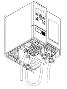
Servo Drive Failure Reason

 What’s Wrong With Drive ?

Industrial electronics, including drives, have a certain lifetime – and the components do too! Aging components is the single most common reason for failure. Capacitors are often the first component to fail. Other likely failure culprits include resistors, diodes, IGBTs, driver ICs, relays, transistors, transformers, opto-isolators, and rectifiers, as well as others.

7 Signs of Servo Drive Failure 

Many component failures in a servo drive are visible to the naked eye, even to the non-technical inspector. The circuit boards are often where the problems are. Failing components may still work but cause intermittent problems. Eventually they will fail completely leaving you in the lurch. Here are seven things to look for that tell you servo drive repairs are likely needed soon, if not immediately, for your drive to function optimally:

  1. Burned spots on the circuit boards
  2. Corrosion
  3. Leaking or bulging capacitors
  4. Component color change often due to overheating
  5. Component date codes that have expired or will soon
  6. Tarnish on leads
  7. Cracked resistors


What About the Invisible Problems?

Visual inspection is the first action to take. However, you may see nothing obviously wrong. So, what next? The next step requires the use of test equipment. Oscilloscopes and multi-meters can be used to test components to see if they are failing or out of spec for other reasons. 

Surge Arrester


How does a Surge Arrester work ?


Surge arresters are devices designed to protect an electrical system in case of an unexpected discharge. Sudden changes in voltage can ruin the delicate components in an electrical system


Surge arresters work as a defense against voltage spikes by diverting the excess of voltage into the ground. It’s best to think of an arrester like a street with two ways. During regular use, the arrester allows voltage to pass through the system as normal. However, when a spike is detected, the arrester redirects the excess through its landline, while also allowing the regular voltage to continue as normal.

In short, it’s a safety device that makes sure your grid continues to work normally even in the case of unexpected spikes. Surge arresters are used to keep buildings safe in case of lightning for example, but they also work for smaller scale surges and as such are great protection.

Soft Starter


Soft Starter – Principle and Working

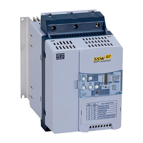
Soft Starters are starting devices, used for the acceleration, deceleration, and protection of the three phase electrical induction motors through the controlling applied voltage to 3 phase motor.

Induction motor is the most frequently used motor for industrial as well as domestic applications. mostly industrial motors are single phase or three-phase induction motor depends upon supply fed to it. Ac motor is become most popular because of its simple and robust construction, low maintenance and can be suitable for any working condition.

Due to its numerous applications, the induction motor needs some starting arrangements to start softly and safely. Various starting methods are used to start induction motors like star delta starterDOL starterauto transformer startersoft starter, and VFD. ( full form variable frequency drive).
In this article we are going to discuss Soft starter for three phase induction motor, soft starter circuit, soft starter working, application, advantages, block, power, control diagram, working principle, uses.
Soft Starter is another form of reduced voltage starter use for starting 3 phase induction motor. Soft Starter also called a Solid-State controller.
Soft Starter does not change frequency as VFD. Instead it Ramp up voltage level applied to motor from initial value to full voltage.

This is the main difference between Soft Starter and VFD (variable frequency drive).

Initially applied voltage is low which is only to overcome gear wheels or stretching driving belts etc. to avoid sudden jerks during the start. Gradually voltage increase, the torque also increases and motor start to accelerate.

Advantages of soft starter starting methods are the possibility to adjust torque as per exact need.
By the use of soft starter starting current reduced, this helps to protect the motor from taking high starting current and also prevents a huge voltage drop in supply. Soft Starter also provides a soft stop as a start. Hence it can be suitable where soft stopping is required like a conveyor belt, water pumps.
The main benefits of using a soft starter are, The inrush current is reduced so that voltage drops on the network are avoided. The torque is reduced which will decrease the mechanical stresses on the equipment and lead to a reduced need for service and maintenance and also to a longer life of the equipment.

Soft Starter Block diagram :

Soft starter single line diagram
Soft Starter contains only a few main components thyristor to regulate the voltage to the motor. In addition to this heat sink and fan for dissipate the heat to the environment.
Depending on the model of the soft starter, it can be equipped with a built-in electronic overload relay (EOL) eliminating the need for an external relay.

Soft Starter working principle:

soft starter working is base on thyristor or SCR firing angle.
Soft starter thyristor bank

soft starter Thyristor firing angle

Thyristor firing angle at starting
Where,
White portion= thyristor OFF
Blue portion= thyristor ON
Soft Starter contains the number of anti parallels connected thyristor. Each phase has a pair of the thyristor.
A thyristor is semiconductor devices which are normally isolation but applying firing signal to gate, they start conducting and allowing pass current and voltage through it.
At a time of start to perform soft starting firing signal is sent to thyristors so that only the last part of each half period of sinusoidal voltage wave is passed through it.
And after the start, firing signal send to earlier and earlier, to allow bigger and bigger part of voltage wave to pass through thyristor.
Eventually firing signal sends after every zero crossings to allowing 100% voltage through thyristor.
During stopping, opposite action is done.
At first, the full voltage is allowed to pass through the thyristors and as the stop initiate, the firing signal is sent later and later allowing less and less of the voltage to pass through until the end voltage is reached. Then no more voltage is applied to the motor and the motor stops.
Start: Thyristor allows part of voltage through it initially and after increase accordingly ramp-up time set for starting.
Stop: Thyristor is in full conducting mode when soft stop begain, voltage decreases as ramp time set for the stop.
Voltage is reduced at starting hence current and torque also decreases.
if the voltage is decreased to 50% of the full voltage, the current will be decreased to about 50% of the maximum current at that speed and the torque will be decreased to about 25% of the maximum torque.

Advantages of soft starter :

Improved Efficiency: The efficiency of softstarter system using solid-state switches is more owing to the low on-state voltage.

Controlled startup: The starting current can be controlled smoothly by easily altering the starting voltage and this ensures smooth starting of the motor without any jerks this is big advantage of the soft starter.

Controlled acceleration: Motor acceleration is controlled smoothly using a soft starter.

Low Cost and size: This is ensured with the use of solid-state switches.

What is VFD?

Variable Frequency Drive – A variable-frequency drive (VFD) is a system for controlling the rotational speed of an AC motor by controlling the frequency of the electrical power supplied to the motor.

Other names you may have heard:

  • Variable Frequency Drive (VFD)
  • Variable Speed Drive (VSD)
  • Adjustable Frequency Drive (AFD)
  • Adjustable Speed Drive (ASD)
  • Freq. Drive (Frequency Drive)

Types of Bearings: Definition, Function, Uses, Advantages & Disadvantages

Introduction of Barings

Types of Bearings:- The equipment in the industries is made of small-small parts. These parts are assembled to make full of working equipment. Today we will talk about one of the major small parts of such equipment. Today we will talk about Bearings.

Bearings are a very small and crucial element. Different types of bearings are available based on our requirements. It is used to restrict degrees of freedom of any part. It gives the desired direction to a given component. The simplest example is the drawer of your computer table where bearing gives linear motion to a component. Bearing eliminates direct contact of two parts and reduces friction between them. This also causes less force work or energy to remove a part. Now, let’s discuss different types of Bearing.

Types of Bearings

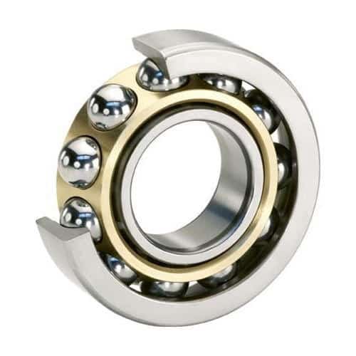
1. Ball Bearings: ( Types of Bearings )

Ball Bearing
Ball Bearing

The ball bearing is the most common type of bearing. It consists of small metal balls that are located between two metal rings which are known as Races. Balls are also kept in position using an assembly called Cage. Since sliding friction is very high compare to rolling friction ball bearing provides less energy loss. The inner Races and balls are free to rotate and the outer races is stationary. The shaft is fitted inside the inner races and the outer races is fixed to a motor.

Advantages of Ball bearings:

  • Give less resistance
  • Easily replaceable parts
  • Less costly
  • Handle high loads
  • Long life

Disadvantages of Ball bearings:

  • It may break due to shocks
  • Little noisy

2. Roller Bearings: ( Types of Bearings )

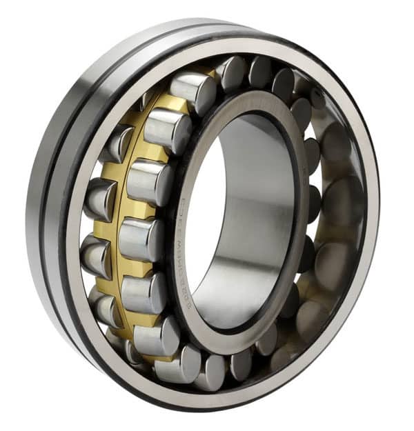
Roller Bearing
Roller Bearing

Advantages of Roller bearings:

  • Low friction
  • High load capacity
  • Easy maintenance

Disadvantages of Roller bearings:

  • Very noisy
  • Costly

3. Linear Bearing: ( Types of Bearings )

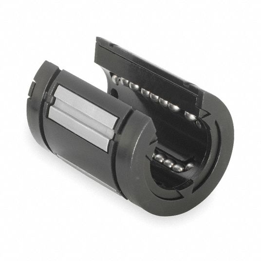
Linear Bearing
Linear Bearing

The linear bearing contains balls or rolling elements between two races but it is used to give linear motion to any component. The simplest example of linear bearing is a Sliding door, Drawer of a cupboard, etc.

4. Jewel Bearings( Types of Bearings ) 

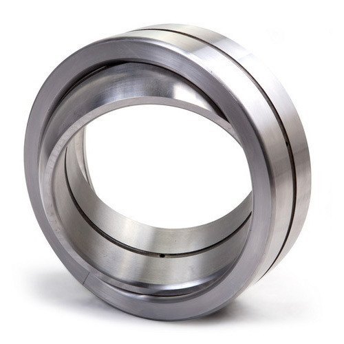
jewel bearing is a plain bearing in which a metal spindle turns in a jewel-lined pivot hole. The hole is typically shaped like a torus and is slightly larger than the shaft diameter. The jewels are typically made from the mineral corundum, usually either synthetic sapphire or synthetic ruby. Jewel bearings are used in precision instruments where low friction, long life, and dimensional accuracy are important. Their largest use is in mechanical watches.

5. Plain Bearings: ( Types of Bearings )

Plain Bearing
Plain Bearing

It is the simplest type of bearing. It consists of a bearing surface and doesn’t contain any rolling elements. The shaft is rotating inside the bearing hole. It provides sliding friction which is greater than rolling friction. An example of it is Shaft rotating inside the bearing surface.

6. Fluid Bearings: ( Types of Bearings )

Fluid Bearing - Types of Bearings
Fluid Bearing

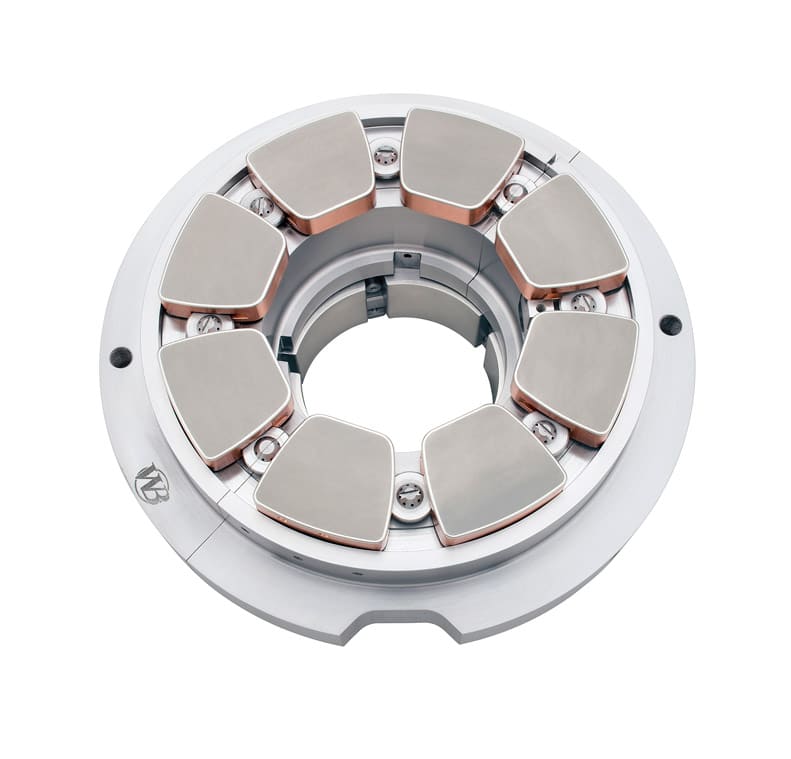
These are the revolutionary type of bearings and currently replacing metal bearings. Here the fluid is subjected to the contact of two-element that reduces friction. Due to fluid pressure, two elements always stay apart and doesn’t come in contact. It provides very less noisy operation and very less vibration than any other metal bearings.

7. Magnetic Bearings: ( Types of Bearings )

Magnetic Bearing - Types of Bearings
Magnetic Bearing

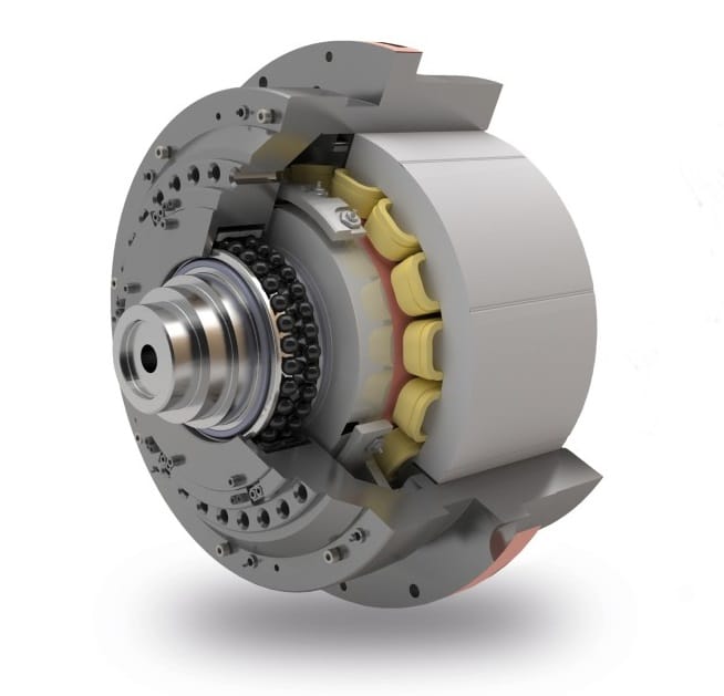
Magnetic bearings use the concept of Magnetic Levitation to keep moving element in the air. It is a very popular bearing because there is no limit to the speed of the rotating element. Two types of magnetic bearings are available one is Active and the other is Passive. In Active type, we use an electric magnet which turns on as shaft moves out of position to take it back to the centre. In Passive type we use permeant or fixed magnet which is difficult to design.

The Different Types Of Gears

A gearbox,  also known as a gear drive, has three main functions: to increase torque from the driving equipment (motor) to the driven equipment, to reduce the speed generated by the motor, and/or to change the direction of the rotating shafts. The connection of this equipment to the gearbox can be accomplished using couplings, belts, chains, or hollow shaft connections. 

Speed and torque are inversely and proportionately related when power is held constant. Therefore, as speed decreases, torque increases at the same ratio.

The heart of a gear drive is the gears within it. Gears operate in pairs, engaging one another to transmit power. Read on to learn the different types of gear and the applications and industries that utilize them.

Spur Gear

Spur gear

Spur gears transmit power through shafts that are parallel. The teeth of the spur gears are parallel to the shaft axis. This causes the gears to produce radial reaction loads on the shaft, but not axial loads. Spur gears tend to be noisier than helical gears because they operate with a single line of contact between teeth. While the teeth are rolling through mesh, they roll off of contact with one tooth and accelerate to contact with the next tooth. This is different than helical gears, which have more than one tooth in contact and transmit torque more smoothly.

Helical Gear

Helical gear

Helical gears have teeth that are oriented at an angle to the shaft, unlike spur gears which are parallel. This causes more than one tooth to be in contact during operation and helical gears can carry more load than spur gears. Due to the load sharing between teeth, this arrangement also allows helical gears to operate smoother and quieter than spur gears. Helical gears produce a thrust load during operation which needs to be considered when they are used. Most enclosed gear drives use helical gears.

Double Helical Gear

Double helical gear

Double helical gears are a variation of helical gears in which two helical faces are placed next to each other with a gap separating them. Each face has identical, but opposite, helix angles. Employing a double helical set of gears eliminates thrust loads and offers the possibility of even greater tooth overlap and smoother operation. Like the helical gear, double helical gears are commonly used in enclosed gear drives.

Herringbone Gear

Herringbone gear

Herringbone gears are very similar to the double helical gear, but they do not have a gap separating the two helical faces. Herringbone gears are typically smaller than the comparable double helical and are ideally suited for high shock and vibration applications. Herringbone gearing is not used very often due to their manufacturing difficulties and high cost.

Bevel Gear

Bevel gear

Bevel gears are most commonly used to transmit power between shafts that intersect at a 90 degree angle. They are used in applications where a right angle gear drive is required. Bevel gears are generally more costly and are not able to transmit as much torque, per size, as a parallel shaft arrangement.

Worm Gear

Worm gear

Worm gears transmit power through right angles on non-intersecting shafts. Worm gears produce thrust load and are good for high shock load applications but offer very low efficiency in comparison to the other gears. Due to this low efficiency, they are often used in lower horsepower applications.

Hypoid Gear

Hypoid gear

Hypoid gears look very much like a spiral bevel gear, but unlike spiral bevel gears, they operate on shafts which do not intersect. In the hypoid arrangement because the pinion is set on a different plane than the gear, the shafts are supported by the bearings on either end of the shaft.
Type of GearsIndustriesApplications
Spur Gear
  • Food
  • Beverage
  • Automotive
  • Forest
  • Energy
  • Unit handling
  • Small conveyors
  • Package handling equipment
  • Farm machinery
  • Planetary gear sets
  • Automotive

Helical Gear
  • Cement
  • Food
  • Beverage
  • Mining
  • Marine
  • Energy
  • Forest
  • Bulk material handling
  • Medium to large conveyors
  • Mixers
  • Large pumps
  • Water treatment
  • Crushers

Double Helical Gear
  • Mining
  • Marine
  • Heavy industry
  • Milling
  • Steam turbines
  • Ship propulsion
 
Herringbone Gear
  • Mining
  • Marine
  • Heavy industry
  • Milling
  • Steam turbines
  • Ship propulsion
 
Bevel Gear
  • Cement
  • Food
  • Beverage
  • Mining
  • Energy
  • Bulk material handling
  • Medium to large conveyors
  • Mixers
  • Crushers
  • Water treatment

Worm Gear
  • Food
  • Beverage
  • Automotive
  • Forest
  • Energy
  • Unit handling
  • Small conveyors
  • Package handling equipment
  • Farm machinery

Hypoid Gear
  • Cement
  • Food
  • Beverage
  • Mining
  • Energy
  • Bulk material handling
  • Small to medium conveyors
  • Small mixers
  • Crushers
  • Water treatmen