HOW INCREMENTAL ENCODERS WORK

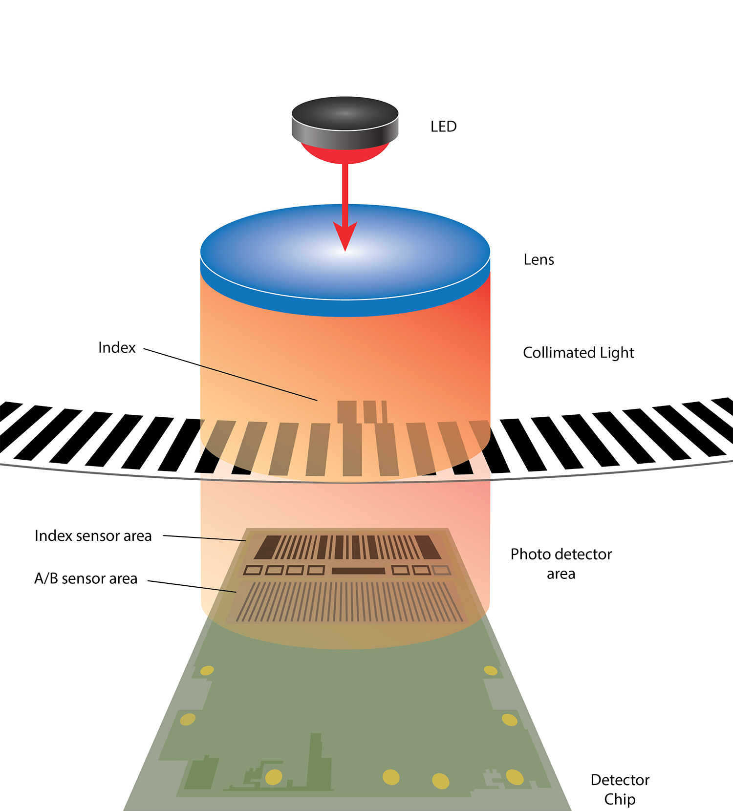
Our incremental encoders have an LED on one side of a transparent disk and a photo detector chip
on the other. The disk has a series of lines and windows on it. The windows allow light to be
transmitted from the LED to the chip. The lines do not. This alternating pattern of light is how the
encoder reports position information back to the mechanical system.
Each set of lines and windows looks identical. Incremental encoders can determine relative shaft
position based on the number of windows and lines that pass in front of the detector chip. If power
is lost and then restored, that relative position is lost.
In some applications - for instance when using an encoder to determine speed, distance or
direction of movement - this may be perfectly fine.
In other applications an exact position is needed.
The only way for an incremental encoder to report its exact position after it’s been power cycled is
for the shaft to rotate until the encoder reaches Index (if it has one).
If designing a system where it’s critical that you know the exact shaft position, including after power
to the encoder has been cycled, you should consider an absolute encoder.
HOW ABSOLUTE ENCODERS WORK
Absolute optical encoders use an LED array, optical disk and photo sensors, like an incremental
encoder but the disks patterns are slightly different.

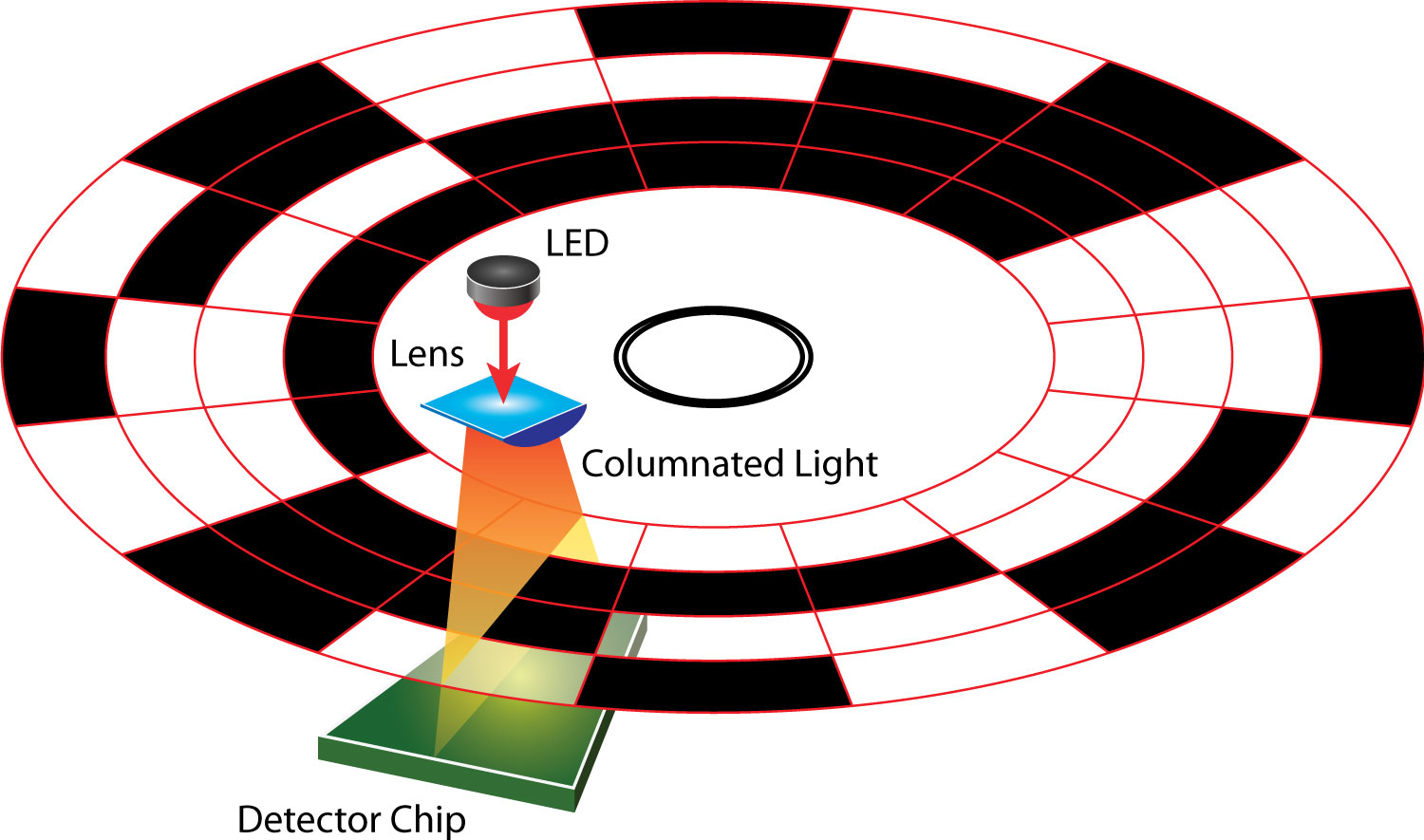
Some designs use multiple bands to create a unique pattern at each point on the disk. For
instance, using the photo above you can imagine that each position can either have a 1 or a 0,
depending on whether the photo sensors detects light from the LEDs. The disks current position
would be 1001, which does not occur anywhere else in the shaft rotation.
